Formula SAE spool statics - chain tension, bearings, and bolt torque
MATLAB scripts for Lehigh Racing LR21 drivetrain statics - chain back-tension, spool shear/moment, Von Mises stress, and mount bolt specs.
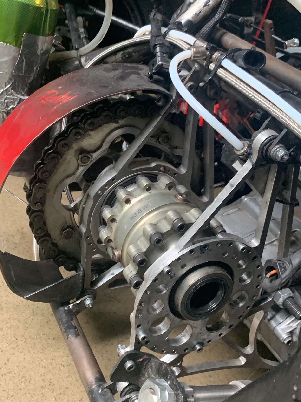

During work with Lehigh Racing, a recurring problem on the rear end was how much load the spool actually sees. Not peak engine torque in isolation: the combination of chain tension, asymmetric bearing reactions, bracket geometry, and chain wrap that decides whether a shaft, a diff mount, or a bolt becomes the weak link.
That work became a small MATLAB suite: spool-static-calcs. The repo README still says unfinished, and it is: but the scripts were used in earnest for LR21 drivetrain decisions and remain a useful snapshot of how the team reasoned about static loads before FEA became the default answer.
Project dossier (scope, timeline, BOM): FSAE Spool Statics Suite.
Why statics first
Formula SAE rewards weight and reliability under real loading - acceleration, braking, and left-turn wheel lift all show up in the rear axle. A spool (or locked diff) simplifies the power path but concentrates force: one sprocket, two bearings, a shaft spanning unequal standoff distances, and brackets tied back to engine and chassis hard points.
Before committing to wall thicknesses and bolt patterns, the team needed numbers tied to CAD geometry:
- Maximum chain tension from engine torque and sprocket radius
- Reaction forces at left vs. right diff bearings (they are not equal)
- Shear and bending moment along the spool between bearing planes
- Per-tooth chain forces from wrap angle and back-tension decay
- Von Mises stress and a static safety factor at critical sections
- Clamping force and installation torque for eccentric mount bolts
MATLAB was the fastest loop for that - change a length in millimeters, re-run, compare to yield.
What is in the repo
The GitHub repository is five .m files, each scoped to one slice of the problem:
| Script | Role |
|---|---|
LR21_Drivetrain_Forces_V1.m | Chain tension from torque; bearing reactions; shear and moment along spool segments |
LR21_Drivetrain_Forces_V2.m | Extended bracket analysis - 2D link geometry from CAD, diff mount reactions, member forces |
LR21_Drivetrain_Backtension_V1.m | Chain back-tension per engaged tooth; force decay around sprocket wrap |
LR21_Drivetrain_Stress_V1.m | Combined bending + torsion to Von Mises stress and static safety factor |
LR21_Drivetrain_TorqueSpecs.m | Friction-based bolt clamping and installation torque for diff mounts |
Naming uses LR21 (Lehigh Racing 2021 car). Several inputs reference prior-season reports (e.g. X49/X50 drivetrain notes) - typical FSAE handoff where you inherit assumptions and re-validate.
Chain tension and bearing split
The force scripts start from engine output torque and drive sprocket diameter:
F_T = T_engine / d_sprocketThat single tension vector does not load both bearings equally. Standoff from sprocket plane to left and right bearing centers creates a moment arm - sum moments about one support, solve for reactions, then build shear (V) and moment (M) diagrams across bearing widths treated as distributed loads.
That pattern answers questions like: where is peak bending, and does the inner left bearing plane see more shear than the outer right? For LR21 geometry, the left bracket could see substantially more reaction than the right - a fact easy to miss if you only analyze symmetric simply-supported beams from a textbook example.
Back-tension around the sprocket
LR21_Drivetrain_Backtension_V1.m implements the familiar roller-chain model: given initial tension T0, tooth count N, pressure angle theta, and wrap over k engaged teeth, back-tension at tooth i decays as:
T_k(i) = T0 * (sin(theta) / sin(theta + 2*beta))^(i-1)Force on each tooth is the difference between adjacent T_k values. The script plots force per tooth and resolves components into vehicle axes using chain angle (~−18.5° in the XZ plane for the LR21 layout). Teeth far around the wrap carry negligible incremental load: the script focuses on the first ~20 engaged teeth where the gradient matters for sprocket and hub design.
This is the kind of analysis that does not show up in a pretty CAD render but does show up when someone asks why the first engaged teeth look battered after test day.
Stress check and bolt specs
The stress script combines bending moment (from the shear/moment work) and shaft torque into principal stresses, then Von Mises, against material yield - Shigley-style, with explicit inner/outer diameters for tube-and-spool sections. Stress concentrations are deliberately ignored; the comment in-file calls out evaluating separate sections instead - honest scope boundary for a static first pass.
LR21_Drivetrain_TorqueSpecs.m closes the loop to hardware: bearing reactions to eccentric mount torques to required normal force on friction plates to per-bolt clamp load and installation torque (M8 example, friction coefficient from Shigley tables). That is the bridge between “the shaft is fine” and “mounts were torqued correctly at assembly.”
Limitations (read the README)
The repo is unfinished by design and by schedule:
- No dynamic load case matrix (braking-only, accel-only, combined)
- No GUI: unlike the tire simulation tooling, these are straight scripts
- Geometry is baked in as numeric CAD exports; changing the spool layout means editing coordinates manually
- Stress concentrations, fatigue, and load factors are simplified or omitted
For a student team shipping a car on calendar time, that was acceptable: statics to bracket the design space, then judgment, test data, and targeted FEA on the final concept.
Using it today
Clone the repo, open MATLAB (or Octave with compatibility caveats), and run scripts top to bottom. Replace torque, material Sy, sprocket tooth count, and CAD-derived lengths with your car’s values. Treat outputs as comparative - the value is tracing which parameter moved the safety factor, not treating SF = 2.17 as gospel.
If you are on a Formula SAE drivetrain subteam and staring at a spool CAD wondering where to start, this is the spreadsheet you wish someone had left behind - except it plots chain tooth forces and writes bolt torque to the console.